Simulation-based analysis for cyclonic separators
Background
Cyclones are widely used for the removal of particles from fluid flows in several industrial processes. Despite its simple operation, the fluid dynamics and flow structures in a cyclone separator are very complex. Currently, with new engineering applications of cyclones, industries require an integrated understanding of the internal flow, structural analysis and particle separation efficiency.
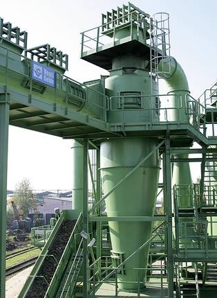
PRE Technologies have developed a comprehensive set of computational analysis tools for the evaluation of the performance of these separation systems. These tools are also of great use in the optimisation of existing systems, through the selection of the most effective retrofit modifications leading to an improvement in the system’s performance.
Methodology
The hydrodynamic model of this type of systems is built using 3D CFD simulations of the internal flow. Discrete phase modelling (DPM) is used to explicitly simulate the transport of solid particles and their interaction with the fluid and the walls of the device. These simulations can be used to locate zones that are more affected by erosion and to estimate the rate at which erosion in the surface will occur. An erosion rate of the particles can be estimated from erosion law models.
These erosion models make use of the impact velocity and angle of impact estimated from CFD simulations as well as the physical properties of the particles and the wall. Different parameters for the erosion models can be obtained from international standards (DNV RP O501 – REVISION 4.2 – 2007) for different cases.
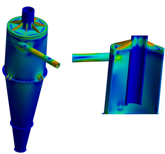
In addition to the modelling of the fluid hydrodynamics, the impact of the fluid operations on the cyclone structure can also be assessed by FE analysis.
Example
Geometry and case study
In this case study, the internal flow of a standard cyclone separator was investigated. This cyclone separator is used for the separation of solid particles from a water stream.
This device uses a tangential inlet pipe to the main body for generating the rotational flow inside the equipment. Solids are collected at an outlet at the base of the cyclone. A vortex finder is placed at the top of the cyclone for the outlet of fluid (as shown in the next figure).

Simulation results
The driving force for particle separation is the strong swirling-turbulent flow generated when both the fluid and solid particles enter through a tangential inlet at the upper part of the cyclone. The tangential inlet produces a swirling motion of fluid, thus developing a centrifugal force field which causes particles more dense than the fluid to move radially outwards from the centre of rotation and downwards in the direction of the base of the cyclone. The solid particles leave the cyclone through a duct at the base of the cyclone while the fluid swirls upward in the middle of the cone and leaves the cyclone from the vortex finder.
The next figure shows the flow rotation generated in the cyclone chamber, caused by the injection of water and particles.

The next figure (left hand side) shows the solid particles trajectories in the cyclone. Simulation results show, as expected, solid particles being pulled towards the walls. For the selected operational conditions and particle size, simulation results also show a preferential path where particles circulate in the conic section of the cyclone close to the base.


On the previous figure (right hand side) we can also see the simulation results of the release of sand particles at the inlet of the cyclone. The highlighted zones in red correspond to zones with higher erosion rate and where the surface damage occurs due to the repeated particle impacts.
Finally, the next figure shows the stress distribution in the solid elements of the cyclone. Simulation results show that the stresses are essentially localised at the inlet tangential pipe, the inlet into the main body of the cyclone, and at the ribs on the top lid of the cyclone. The bolted supports experience moderate stresses.
Benefits of computational analysis
PRE Technologies’ expertise in multiphase flow and component analysis can prove extremely useful in identifying strengths and weaknesses of a product as well as identifying and assessing design modifications.
The benefits of these 3D computational approaches to analysis are the greater insight into local and large-scale issues which may arise in the installation and operation of this type of equipment.
The combined benefit of an integrated fluid and structural analysis can be instrumental in optimising project running times and yield significant cost savings.
Please see other related articles and case studies available at the PRE Technologies website. We are constantly updating our website and aim to have a wider range of case studies in the future, so do keep in touch.
Keep your curiosity in good shape.
For more information on this or any other technical white paper, please contact us.


