CFD/FEA based evaluation of vortex-induced-vibration (VIV) risk
Riser VIV challenges
With offshore oil and gas production venturing in ultra-deep water environments, a number of technical challenges are emerging and there is an increasing need to constantly adapt existing design methodologies. Riser designs in particular are becoming more varied, incorporating a wider range of riser geometries and installation arrangements such as flex-joint drilling risers, steel catenary risers and top-tension risers. The design, installation and operation of these complex riser systems can be challenging partly due to the problem of vortex-induced-vibration (VIV).
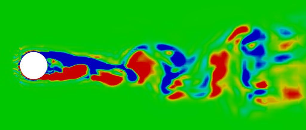
In many new deep-water oil/gas developments, such as the Gulf of Mexico, Brazil's Campos Basin and the Angola’s Gulf of Guinea developments, drilling and production risers are designed to operate in severe sea current climates, with speeds in the range of 0.5m/s - 1.2m/s being encountered. As a result of these high current speeds, the flow around the riser geometry becomes detached creating an unsteady wake with vortices being periodically shed from the riser body. Vortices are alternately shed from one side to another, at a shedding frequency which is linearly proportional to the flow speed, leading to the formation of a von-Karman vortex street (Figure on the right).

As a result of vortex shedding, fluctuating pressure and shear forces are generated on the riser body at a frequency corresponding to the shedding frequency. If this shedding frequency is close to the natural frequencies of the structure’s main vibration modes, then vortex-induced-vibration (VIV) occurs, with the forcing frequency being resonant with the vibration of the structure. This usually manifests in the form of cross-flow vibrations of the riser at or near its natural frequency. VIV if not addressed can lead to fatigue damage, shortened riser design life and increased operational costs. Considerable effort is therefore expended to ensure that the riser arrangement, design detail, vessel/platform layout and proposed installation methods are all suitably designed to avoid VIV.
In assessing and mitigating the risk of VIV occurrence, designers traditionally rely on industry standard tools such as SHEAR7 and VIVA, to gain a better understanding of riser performance. These tools are themselves based on a number of experimental studies of vortex-induced vibration for typical riser geometries, the majority of which are however confined to small scale models of vortex induced vibration in sub-critical flow with low Reynolds numbers. The use of scaled models introduces some uncertainty due to scaling errors and there is an increasing awareness of the need to move to full-scale modelling. The applicability of these existing experimental measurements (and by extension the tools/correlations derived from them) to complex real world installations, such as riser clusters with interaction effects, is also increasingly being questioned. Another emerging constraint to traditional approaches is that with riser installations being carried out in deeper waters with stronger currents, engineers are increasingly concerned with VIV in the critical and post-critical flow regimes for which relatively little experimental data is available.
In response to these challenges, full scale testing and in-service monitoring is becoming more prevalent in order to develop a better understanding of riser performance in real world condition. This however comes at a considerable cost and if adequate prior knowledge of expected behaviour ranges is not available, this can introduce significant modification costs late in the project development cycle.
There is therefore a need for engineers to be able to quickly evaluate a number of possible VIV related design configurations at the FEED stage in order to inform the overall design layout and reduce the level of risk/uncertainty in the designs. Computational mechanics simulations, such as CFD and FEA are ideal for this type of analysis and are increasingly being used to assess the likelihood of VIV occurring and evaluate the effectiveness of various suppression strategies.
CFD/FEA based assessment
Recent advances in CFD turbulence modelling, with the emergence of hybrid URANS/LES models, have made the reliable engineering simulation of turbulent critical and post-critical flows a reality. CFD models can be used to relatively quickly and cost effectively (compared to full-scale testing) simulate a full-scale design configuration involving complex geometries, high flow speeds and complex or varied riser arrangements. This allows engineers to gain deeper insights into the nature of the complex turbulent and three-dimensional flow field as well as the unsteady hydrodynamic loading on the structure due to vortex shedding.
Using the CFD-predicted hydrodynamic loading together with signal processing techniques, the forcing frequency due to vortex shedding may be obtained. This forcing frequency information together with an FEA based modal analysis of the riser configuration, to obtain the structural mode shapes and natural frequencies, can be used to assess the likelihood of VIV occurring in a given riser configuration.
If VIV is deemed to be likely, riser modifications aimed at VIV suppression can again be rapidly incorporated into the model and evaluated using CFD in order to assess their effectiveness.
PRE Technologies engineers have a wide range of experience in flow induced vibration problems including VIV. This case study highlights the application of CFD and FEA modelling techniques to a cylindrical cross-section that is representative of a typical marine riser. A conservative current speed and riser diameter are assumed, to give a flow well within the post-critical range with a Reynolds number of 2.5E6. To accurately simulate the flow around the geometry, an incompressible 3D turbulence model of a section of the riser is taken. A minimum 6D (six diameters) cross-section is required to ensure independent results.
First a bare riser geometry section is modelled in order to determine the forcing frequency due to vortex shedding. A helical strake attachment is then designed according to best practices and incorporated into the riser body and its effectiveness assessed using CFD.
In order to capture the separation effects as well as the multiple turbulence length scales involved with the flow, a fine numerical grid is required, and meshes of up to 2.5 million cells have been used in this case study. A CFD code is used to solve the unsteady Navier-Stokes equations, with a DES turbulence model that directly simulates the turbulent length scales that are resolvable, while employing a URANS approach to model the unresolved scales.
Bare riser model results

The complex three-dimensional flow around the bare riser is computed and the figure on the right highlights the coherent turbulent flow structures in the wake of the riser. The flow is a result of a complex non-linear interaction across a range of turbulence scales.
Using a robust CFD approach to capture these effects results in the accurate simulation of the frequency composition of the hydrodynamic loading on the riser body. Figure on the bottom left shows a segment of the hydrodynamic lift (cross-flows direction) coefficient time-series generated from the bare riser simulation. A FFT of the lift coefficient signal is used to extract the frequency composition and determine the dominant forcing frequencies acting on the riser body (figure on the bottom-centre).
An FEA based modal analysis of a 30m long riser geometry is also carried out and used to determine the first 5 major vibration modes and their respective frequencies as shown in the figure on the bottom-right. The VIV forcing frequency of 3.4 Hz is shown to coincide with the 2nd vibration mode of the riser which has a natural frequency of 3.3 Hz. Under the flow conditions considered, the bare riser is therefore likely to enter into VIV in the second vibration mode.


Helical strake design assessment
In order to reduce the likelihood of VIV, a helical strakes has been incorporated as a means of suppressing VIV. A properly designed helical strake can be effective in suppressing VIV and CFD methods offer a reliable too for use in helical strake design and optimisation.

The success of a helical strake design is based on its ability to effectively disrupting the simultaneous separation of the flow which produces spatially correlated (in the axial direction) hydrodynamic forces on the riser surface. It is these correlated pressures which produce a coherent forcing field that leads to VIV.
The next figure shows the resulting flow structures surrounding the riser with the helical strake installed. The flow is characterised by much smaller scale structures in the vicinity of the riser surface which are less correlated than in the bare riser configuration and hence less likely to lead to VIV. The riser surface pressures are also shown to be less correlated in the axial direction for the rake arrangement than with the bare riser configuration.
Contact us for more information on fluid induced vibration or any other subsea challenge.
Keep your curiosity in good shape.
For more information on this or any other technical white paper, please contact us.


