CFD based analysis of fuel cells
Background
Much work has been done to optimise Fuel Cell systems and with the increase of computer power, modelling started to play a key role. Recently, engineers have been using complex 3D models to address the main concerns regarding fuel cell optimisation, such as heat management, water flooding in low temperature stacks or air flow rate optimisation.
In this paper, PRE Technologies present their capabilities in the computational modelling of fuel cell systems with two examples. In the first one a serpentine flow channel, used typically in low temperature PEM fuel cells, is modelled to investigate the effect of liquid water in the channels. In the second example, a full fuel cell stack is modelled to assess the impact of the air flow rate on the temperature distribution within the stack.
Flow channel model
Low temperature PEM fuel cells produce large quantities of liquid water at the cathode which must be removed via flow channels. If this removal is not efficient the fuel cell cathode can flood with catastrophic consequences in terms of performance. To reduce operating costs the cathode side normally works at atmospheric pressure or slightly above. Therefore, in the event of water blockage, the inlet pressure is not sufficient to push the water towards the outlet. Flow channels should be designed to minimise water accumulation and at the same time ensure a homogeneous oxidant distribution though the active area.
Methodology
A 3 dimensional, multi-phase and dynamic model was developed to address the liquid water transport in the cathode micro channels. The computational domain consisted of a serpentine topology with 3 parallel channels, as shown if in the next figure.

The volume of fluid (VOF) approach was used to model the multi-phase flow and due to the very low velocities in the channels no turbulence equations were added to the Navier-Stokes equation to solve the momentum balance.
Liquid water droplets were added to the domain at t=0 s and their evolution towards the domain outlet was captured over 1.8 s.
The following operating conditions were tested:

Results
For both cases water accumulates at the 90° bends, however, in Case A the rate of accumulation is higher, as can be seen in the next figure. This fact is directly related with the inlet air velocity, with the increase of air velocity more water is dragged, therefore less will gather in the corners.

The next figure shows the effect of liquid water in the inlet pressure for Case A. Pressure oscillates with time and an overall pressure increase is observed when compared with the results for the case where liquid water is not present. Although pressures are not too high in magnitude, they can lead to structural failure at extreme conditions, especially considering that flow fields for low temperature PEM fuel cells are normally made out of carbon or carbon composites a few millimetres thick.

Full Fuel Cell Stack Model
Heat management is one of the most important issues regarding fuel cell stack design. Operating temperature needs to be kept as constant as possible around the predefined value to ensure the desired performance. For instance, solid oxide fuel cells (SOFCs) need to run above 800 °C to ensure its ceramic components become electrically and ionically active. On the other hand, low temperature PEM fuel cells need to run below 80 °C, or else the polymer membrane loses protonic conductivity. In this example, a open cathode PEM fuel cell stack, where air is used as coolant, is modelled to analyse the impact of the inlet air flow on the temperature distribution.
Methodology
For this example a 3 dimensional, single-phase, non-isothermal CFD model was developed. Momentum, mass, species and energy balance was solved and a set of constitutive relations were introduced into the model via user define functions (UDFs) to account for heat generation (exothermal reaction and Joule heat) and species kinetics.
Constitutive relations
When the fuel cell electric circuit is closed with a load in it, the potential is expected to drop from the open circuit potential as a function of current being generated, due to inevitable losses. Potential losses can be caused by different factors but in this example, only two forms of potential losses were accounted for: sluggish electrode kinetics in the cathode, also known as activation polarization, and concentration polarization. Both phenomena can be modelled by the Butler-Volmer equation. Because the charge balance was not modelled a constant current density (i) was assumed and the overpotential (η) was calculated based on that current. The Butler-Volmer equation was rearranged, in order to make the overpotential the dependent variable:

The transport and electrochemical parameters used for this example were extract from Barbir F (2005) PEM fuel cells theory and practice, 1st edn. Elsevier Academic Press, Burlington.
The next figure shows the computational domain.

In this example, constant air velocity and temperature were set at the cathode flow channels inlets and at the outlets atmospheric pressure was imposed. The cathode electrode was modelled as a porous zone with a specific porosity and permeability. The hydrogen in the anode channel was stagnated at a constant pressure.
The following operating conditions were tested:

Results
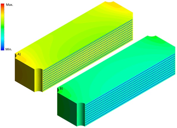
Results show how air velocity affect the temperature distribution in the fuel cell stack. In case A, where the lowest air velocity was used, very high temperatures arise in the centre of the stack. This fact could lead to failure due to the membrane dry out. In addition, thermal stresses could also rise, especially during transient operation. Increasing the air flow rate proved to be a good solution to decrease temperature gradient in the stack.

The next figure presents the results for the temperature through the middle bipolar plate (left) and the temperature through the middle of the cathode channels (right).

Benefits of using CFD
Computational modelling of the fluid flow in fuel cell system was shown to be a valuable tool in the evaluation of the performance, optimisation and in the detection of problems.
The analyses presented here could potentially be used in the optimisation of existing systems as well as in the design of new stacks. PRE Technologies have the capabilities and knowledge to customise this methodology to any kind of fuel cells systems.
Please see other related articles and case studies available at the PRE Technologies website. We are constantly updating our website and aim to have a wider range of case studies in the future, so do keep in touch.
Keep your curiosity in good shape.
For more information on this or any other technical white paper, please contact us.


