Simulation-based analysis for gravity separators
Background
Different types of surface facilities are used for phase separation in the oil industry. The physical separation of oil and water in the oil production process is usually carried out in horizontal three-phase separators. These tanks consist of large cylindrical vessels designed to provide sufficient residence time for the separation of liquid droplets by gravity.

The design of these types of separators is usually based on semi-empirical correlations and guidelines (such as the KLM EDG: Separator Vessel Selection and Sizing – Revision 01 – 2011). Computational fluid dynamics (CFD) techniques can prove useful in understanding important flow mechanisms in the separator and thus predict its performance.
PRE Technologies have developed a set of computational analysis tools that can be used in the evaluation of the performance of these separation systems. In this case study, the performance and internal multiphase flow behaviour in a three-phase separator was investigated.
CFD simulation of the internal flow
Modelling approach
The hydrodynamics model of this type of systems is built using 3D CFD transient simulations of the internal flow. This model makes use of the Volume of Fluid (VOF) approach to simulate the transport of the different phases through the separator.
Geometry
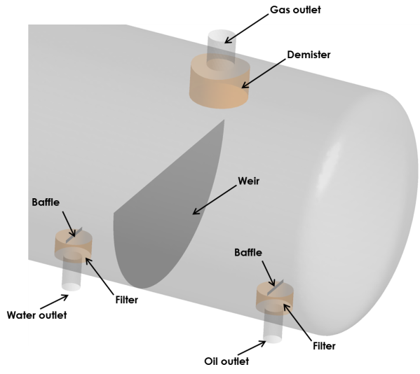
The next figure shows the geometry used for this case study. An inlet baffle is positioned at the vessel inlet which considerably dampens the inlet velocity (slug catcher). The baffle acts as a momentum diffuser by scattering the inlet jet. A perforated screen is used to retain any solid particle present in the main stream. This screen is also useful to stabilize the oil-water interface by forcing the mixture towards quiescent conditions, enhancing separation mechanisms of coalescence and settling.

The next figure shows a detailed view of the outlet region of the vessel. A filter is used at the water and oil outlets to trap solid particles. A baffle was placed at the top of the outlet to suppress the formation of vortices. A demister is positioned at the gas outlet.

Results
The next set of figures show the separation of the oil-water mixture in the vessel. Water migrates to the bottom of the vessel and leaves through the water outlet placed before the weir. Oil's free surface rises above the weir and falls in the second chamber, leaving the vessel trough the oil outlet.

At the inlet, the mixture impinges in the inlet baffle. The jet is dissipated generating a high turbulence region at the beginning of the separator. The next figure shows the decrease of velocity magnitude in the liquid-gas interface.

The next figure shows the pathlines of gas in the upper part of the separator. Simulation results predict a recirculation of gas after the inlet baffle. Results also show gas entrainment after the weir caused by the oil falling in the second chamber of the vessel. Nevertheless, the gas entrainment is not deep enough to allow for gas to escape through the oil outlet.

Structural analysis
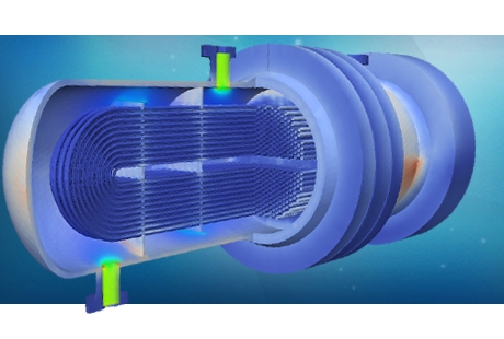
In addition to the modelling of the fluid mechanics, the impact of the fluid operations on the structure can also be modelled. The next figure shows typical stress linear analysis results.

By determining the stresses and deformations in the vessel body and its subcomponents, it is possible to verify the structural integrity of separator design in response to pressure and thermal stresses and other fluid loads. Additionally, cyclic loading and stress concentrations can be analysed to assess the fatigue resistance and expected life of the product and its subcomponents.

Compliance with international Standards is a specific expertise of PRE Technologies, with numerous projects involving validation to AMSE VIII and EN-13445.

Benefits of computational analysis
PRE Technologies’ expertise in multiphase flow and component analysis can prove extremely useful in identifying strengths and weaknesses of a product as well as identifying and assessing design modifications.
The combined benefit of an integrated fluid and structural analysis can be instrumental in optimising project running times and yield significant cost savings.
Please see other related articles and case studies available at the PRE Technologies website. We are constantly updating our website and aim to have a wider range of case studies in the future, so do keep in touch.
Keep your curiosity in good shape.
For more information on this or any other technical white paper, please contact us.


