Thermo-mechanical fatigue modelling white paper
Background
Pressure equipment is often subject to cyclic loading during service, accumulating irreversible damage due to degradation of the material in response to alternating stresses. This type of loading can lead to the initiation of cracks, which may propagate resulting in sudden failure of the structure at stress amplitudes lower than the tensile yield strength of the material. This mode of failure can be predicted assuming conservative rules with the combined use of the Finite Element Method (FEM) and fatigue theory.
Different types of loads can lead to fatigue failure. Temperature and pressure oscillations are usually included in the design specification of vessels and other pressure equipment together with other mechanical loading oscillations. Relevant technical standards propose a clear methodology to conduct calculations including stress and fatigue failure prediction. In particular ASME VIII-2 and PD-5500 are widely used for these purposes. Standards and codes also provide the input needed to post-process the stress distribution calculated by the FEA method.

The fatigue analyst of pressure equipment must pay extra attention to some geometric features like welds, bolting, clamps and supports as these detailed areas will probably be the ones limiting the fatigue useful life of the entire system. The use of codes will aid the analyst in this matter as standards normally provide a set of curves (S/N curves) that include the information gathered after numerous tests of specimens containing welds and other features similar to those under consideration.
The calculation methodology usually includes two main stages:
- Linear elastic thermal-mechanical coupled FEA to calculate the stress ranges in response to the different loads
- Fatigue analysis using PD-5500 or ASME VIII-2 codes to ensure the design complies with the minimum operational life of 25 years
Technical approach
PRE Technologies specialises in the finite element analysis (FEA) approach to perform stress and fatigue analyses of pressure equipment under the loads specified by the client with the objective of assessing the expected useful life for the different components or assemblies.
The analysis of the different assemblies involves the use of FEA coupled methods. The outputs from the stress analysis are used to complete a fatigue analysis in accordance with the methodology contained within the PD-5500 or ASME VIII-2 codes. The steps that are followed along the technical delivery of the project are discussed below (for PD-5500 only).
FEA modelling
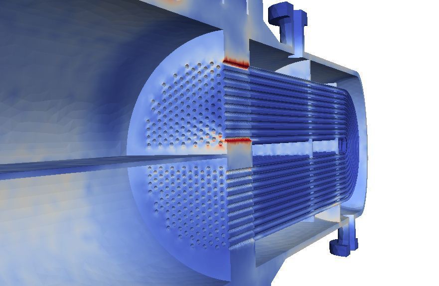
The work is based on the examination of the thermally and mechanically induced stresses on the equipment for a whole cycle. To facilitate the analysis two different FEA models are created. The first model will be used to calculate the temperature field on the vessel or reactor under the given conditions and the second will add other cyclical mechanical loads to obtain the alternate stress that will eventually lead to fatigue failure. A third stage might be required to evaluate the locally relevant stresses where the global model accuracy is deemed not sufficient.

A summary of the stages involved is detailed in the next list:
- Generation of 3D model geometry from the equipment drawings
- Construction of two different sets of meshes suitable for capturing the overall elastic and thermal response of the system
- Calculation of the temperature field distribution from the boundary conditions using linear thermal FEA
- The temperature field is then mapped within the thermo-mechanical model to calculate the final combined loading state coupling the thermal and the mechanical cases to identify the most critical regions and calculate the stress field
- Generation of a static linear mechanical model to calculate the initial stress state due to the external forces the assembly is subject to, including the thermal loads
- Obtain the stress historical evolution for the whole vessel/reactor cycle and evaluate the amplitude and number of cycles for each identified critical region using a counting method
- Post-process the FEA stress ranges to obtain the fatigue life
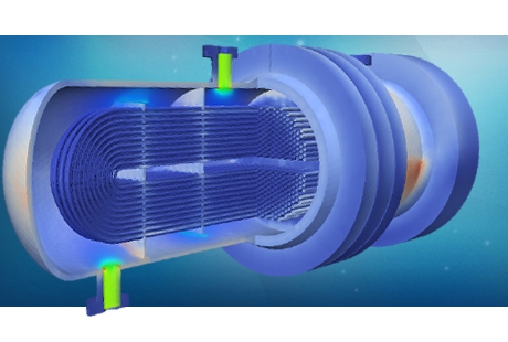
As mentioned, sub-modelling of some regions is often utilised to provide an accurate analysis of stress concentrations due to small features, discontinuities or stress risers not included in the global model. This can be, for instance, the nozzle regions or the baffle/coil welds in vessels and heat exchangers.
Some assumptions are normally made based on PRE technologies’ experience in FEA fatigue modelling:

- No previous fatigue damage is considered. Pre-existing cracks or flaws in the reactor can play significant role in the assessment of the fatigue life, but a different type of analysis is required to evaluate this effect (FEA based crack propagation)
- No degradation of the thickness due to corrosion or erosion is assumed unless otherwise specified
- Refractory material or thermal insulation is included in the thermal model but assumed not to have any stiffness contribution
- Welds are not explicitly modelled in the FEA model, but are taken into consideration in the fatigue assessment
- All materials are assumed isotropic and homogeneous (unless otherwise specified)
- Material properties and S/N curves are obtained from the PD-5500 or ASME VIII standards
- Fatigue reduction factors are used if needed following the recommendations of PD-5500 or ASME VIII standards
Fatigue assessment
The fatigue assessment methodology is based on the recommendations of the standard used (for this example the PD-5500 standard). This standard recommends the use of previously simplified fatigue analysis and screening methodology assuming conservative rules. PRE technologies perform this analysis to assess the need of fatigue evaluation as part of the best practices in fatigue failure prediction methods. The use of FEA models can greatly improve the use of manual calculations normally used in this type of preliminary conservative analysis.
A further detailed analysis is performed using the stress ranges obtained from the FE analysis. This analysis involves more detail and the use of S/N curves to predict the damage factor for each identified set of loads. The first stage in this procedure is to calculate the stress historic of each of the identified critical regions. Principal stresses will be computed and amplitude will be used together with S/N curves to assess the potential fatigue failure.
The fatigue curves in PD-5500 are derived from welded samples tested based on the mean minus two standard deviations of the S-N curves corresponding to 97.7% probability of survival. These fatigue curves basically incorporate mean stress, so the effective stress ranges do not need to be corrected due to mean stresses, leading to a removal of every constant load presented in the cycle considered.
The fatigue curves are associated with figures of welded joints. The direction and location of the principal stress is used to determine which of the seven fatigue curves is to be applied. In the figure on the right the PD-5500 S-N curves for austenitic steel are presented.

The classification of welds and directions of principal stress in complex loading cases are not always obvious. In case of multi-axial stress state governing the cycle, the algebraic difference between the maximum and the minimum stresses regardless of the direction will be assumed as the alternating stress input in the S-N curves. Principle of conservatism is always used by the PRE technologies engineers to ensure the predicted results are within reasonable safety margins.
In order to comply with the specification assessment, the following steps are taken:
- Classification of the material properties for each element in the assembly in accordance with PD-5500
- Calculation of the secondary principal stress amplitude using linearization stress along classification lines for each stage of the cycle
- Use a counting method like “reservoir” or “rain flow method” to accurately count the number of cycles expected for each effective stress cycle
- Include potential correction factors due to material or thickness effects to the alternating stress amplitude
- Assign the proper S-N curve based on the PD-5500 classification included in the Table C.2 of the mentioned document
- Calculate the cumulative damage effect using Palgrem-Miner linear rule to calculate the accumulative damage of each effective stress cycle
- The permissible number of cycles will be subsequently determined for comparison to the allowable cycle number based on the required fatigue life of 25 years
PRE Technologies' engineers possess vast experience applying this methodology to a variety of pieces of equipment, including separator vessels, chemical reactors, compressors, cyclones, spools and pipeline sections.
Keep your curiosity in good shape.
For more information on this or any other technical white paper, please contact us.


