FE and CFD based analysis of spools and jumpers
Background

Spools and jumpers are critical components of subsea production systems (SPS), connecting wellheads, manifolds and riser bases for the extraction of oil and gas in deep and ultra-deep waters.
The subsea sector is mature enough for a reduction of cost and the integration of SURF and SPS is crucial to drive the optimisation of subsea engineering.
PRE Technologies have developed a comprehensive set of computational analysis tools to optimise the safe design of spools and streamline their integration into subsea systems. Examples of these tools are presented below.
Flow assurance
Slug induced fatigue analysis
Slugging can result in cyclic loading in the lines, leading to fatigue damage and possibly significant stresses that need to be considered in the design process.
CFD modelling can be used to investigate slugging events in a given structure. This model makes use of the Volume of Fluid (VOF) approach to simulate the multiphase fluid.
As an example, the next video shows the contours of volume fraction of gas and oil flowing through a spool.
In this case, a separated multiphase flow of oil and gas is observed in the system with several gas pockets being formed and transported along the pipe section. In the long horizontal pipe section, it can be observed that the different formed gas pockets merge and reform as one bubble that stretches along the full length of the horizontal pipe section. In the vertical sections of the pipe, the gas again forms several gas pockets.
The passage of the gas pockets results in a variation of pressure in the system (see next figure). The variation of pressure can be a source of stress amplitudes to be considered in a fatigue analysis.
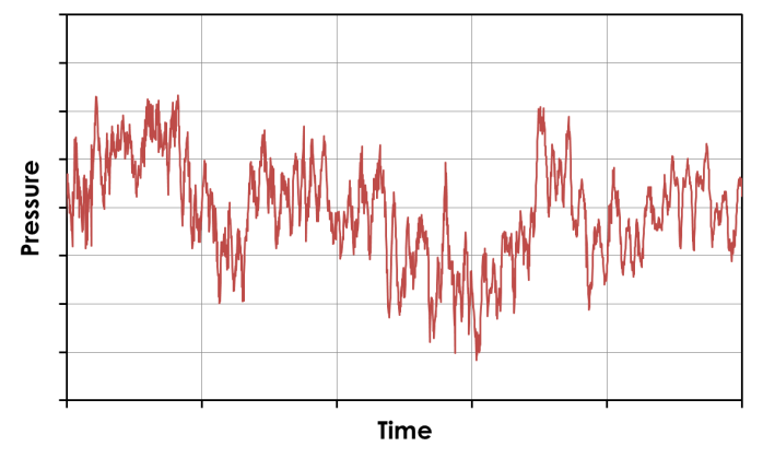
The frequency of the flow can be found by calculating the power spectral density of the pressure variation sampling (see the next figure).

The varying pressure can also trigger resonant modes of vibration in the spool, so it must be ensured that the frequencies excited by the flow do not coincide with the modal frequencies of the system. PRE Technologies integrates the parametric design and stress analysis of spools with the modal analysis and external flow simulation.
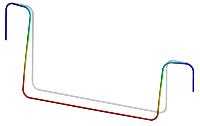
The next figure displays the first vibrational mode of the spool under investigation. Several modes can be rapidly verified and cross checked against a Computational Fluid Dynamics (CFD) internal or external flow simulation. If these modes are excited, a fatigue analysis is seamlessly incorporated in the design process.
Additionally, the stress load case matrix can be combined with information on the spool lifecycle (i.e. operation, start-up, shutdown etc.), to produce stress ranges for a detailed fatigue analysis, using S-N curves, in accordance with international standards (ASME, DNV-RP-C203, DNVGL-RP-0005).
Particle erosion modelling
The transport of solid particles can result in surface damage caused by the repeated application of high localised stresses. The erosion by solid particle impact is a problem of great practical significance since it can result in component failures.
CFD simulations can be used to locate zones of a given structure that are more affected by erosion and to estimate the rate at which erosion in the surface will occur.
Discrete phase modelling (DPM) can be used to explicitly simulate the transport of solid particles and their interaction with the fluid and the walls of the structure.
An erosion rate of the particles can be estimated from erosion law models. These erosion models make use of the impact velocity and angle of impact estimated from CFD simulations as well as the physical properties of the particles and the pipe. Different parameters for the erosion models can be obtained from international standards (DNV RP O501 – REVISION 4.2 – 2007) for different cases.

For example, the previous figure shows the simulation results of the release of sand particles at the inlet of a spool. Simulation results show that erosion happens at a higher rate in the bends of the structure where the flow changes its direction. The inertia of the particles causes the solid particles to impinge on the walls of the pipe, resulting in a measurable erosion rate (mm/year).
Mechanical design
The mechanical design of rigid subsea spools can be complex due to the variety of loads which they are subjected and their position in subsea developments. Spools and jumpers connect the principal subsea structures such as Manifolds, Christmas Trees (XT) or Riser Bases to Pipeline End Terminations (PLET). They must be strong enough to sustain operational, hydrotest and accidental loads whilst maintaining sufficient flexibility to accommodate pipeline end displacements, riser motion and thermal expansions, with reactions within connector capacities. Furthermore, the design must optimise the number of induction bends and facilitate transportation and installation.
The mechanical design of spools and jumpers is driven by compliance with international standards (DNV-OS-F101, API 17R & 17TR8, ASME B31.4 & B31.8). Typically, checks are required for the following loads and failure modes:
- Internal (burst) and external (collapse) pressure resistances
- Thermal expansion
- Soil friction
- Riser motion (e.g. hybrid risers)
- Installation tolerances
- Lifting
- Dropped object
- Flow Induced Vibration (VIV, slugging, etc.) & Fatigue
PRE Technologies possess the required experience and computational tools to condense the required analyses and produce safe and compliant spool designs.
Stress analysis of spools can be setup to rapidly cover all required load cases, optimising the design iterations on the geometry via parametric analyses. For example, the next figure shows the FEA results for a spool subjected to internal and external pressure, thermal loading and pipeline end displacement. In addition to stresses and deflections, the analysis also outputs force and moment reactions at the ends, ensuring compliance with the end connector capacity envelope.

Induction bends
A particular concern in the design of subsea spools and jumpers is the requirement to balance strength and flexibility and the impact this need has on the design of the induction bends of the spool.
Induction bends are subjected to large forces during their manufacturing process, which may result in residual stress and a shortened fatigue life. Additionally, they are typically the location of the peak stresses in a jumper. For this reason, analytical design recommendations, such as DNV-OS-F101 Sec 5 F202, are very conservative. This may result in unnecessarily large wall thicknesses for bends, leading to increased materials and transportation costs. The problem is compounded when larger spool spans must be designed to accommodate the reduced flexibility of the thicker bends.
The costly over-conservatism can be avoided by means of a detailed FE analysis to establish the collapse resistance of bends. A non-linear buckling analysis can be performed to ensure that the required collapse capacity is achieved. All significant buckling modes (e.g. next figure) are captured and analysed.

Please see other related articles and case studies available at the PRE Technologies website. We are constantly updating our website and aim to have a wider range of case studies in the future, so do keep in touch.
Keep your curiosity in good shape.
For more information on this or any other technical white paper, please contact us.


