Oil and gas safety
Oil and gas industry is extremely conscious of the risks involved at every step of the oil field development, especially on offshore sites. Health, safety and environmental policies (HSE) and guidelines are strictly followed to prevent human injury and environmental damage during the field lifespan. Prevention and mitigation measures are considered for all stages, from drilling and completion activities to production and processing operation. A hazard and operability review (HAZOP) systematically examines all possible process setups, verifying that the design incorporates adequate safeguards for a safe operation, shut down and re-start.

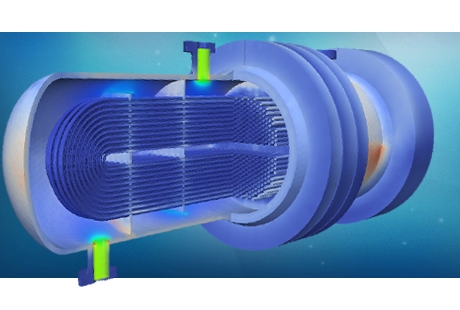
Simulation and mathematical modelling have helped safety engineers design appropriate prevention and mitigation measures for various sources of risk. For instance, CFD analysis has been regularly used to develop kick/blowout prevention studies, to dimension vent/flare systems and to predict gas and oil dispersion in the atmosphere and the sea. FEA has also been used in the prediction of the mechanical integrity of different process equipment in the event of pressure peaks and explosion events.
Blowout prevention
Blowout prevention is a broad term that encompasses anything from the precautionary methods used on rigs to prevent "kicks" from developing, to the use of sophisticated devices called Blowout Preventers (or BOPs) designed to close off a well in the face of an imminent blowout.
 The use of CFD analysis has aided the dimensioning and optimisation of blowout prevention systems and equipment over the years. Kick and blowout development downhole can be predicted and its effect on the wellhead structure estimated using fluid dynamics models. These models take into account the non-Newtonian properties of the drilling fluid as well as the rapid pressure increase on the formation fluids. The results of these models are often the input to mechanical FE Analysis. Stress analysis on wellhead structure and BOP stack (annular and ram preventers) can be carried out using linear elastic as well as non-linear plastic FEA models.
Venting and flaring
Production conditions are often far from stable. Variations in temperature, composition and pressure have to be constantly balanced by the production and processing systems. De-pressuring, high pressure relief, venting and flaring systems have to be put in place and need to react quickly to variations in production conditions in order to prevent hazardous scenarios.
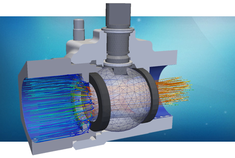
 A relief system is an emergency system for discharging gas to relieve pressures in excess of the maximum allowable working pressure (MAWP). There are a number of industry codes and recommended practices that provide guidance in the dimensioning, selection, and installation of relief devices and systems such as ASME Pressure Vessel Code, Sec. VIII, Division 1. PRE Technologies possess relevant experience in applying these recommendations for the stress analysis on a variety of relief valves, including rupture disk and spring-loaded valves.
The de-pressuring/relief system control valves may be arranged to discharge into the flare drum or directly into the atmosphere. In the case of a gas discharge to the atmosphere the possibility of freezing and hydrate formation during high-pressure releases should be considered. Joule-Thomson cooling models help designers predict and measure this effect and modify the design or the operation configuration of these devices. Additionally the location of these venting devices must be carefully studied. CFD analysis is typically used to evaluate the gas dispersion on a variety of ambient conditions of temperature, wind speed and wind direction.
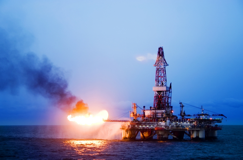
A flare system collects, burns and discharges gas from a pressurized process components to the atmosphere. Stronger environmental regulations have eliminated continuous flaring in many areas. Vapours and flare gas are now normally recovered, and only in exceptional situations does flaring occur. Flaring is a complex process whose design involves a variety of engineering disciplines.
 Thermal/radiation calculations on the flare tip, corrosion on the flare tip, and flashback effects are some of the aspects that need consideration when designing a flare system. CFD models are broadly used for these considerations following the guidelines of API 521. Flare performance in a variety of operational and ambient conditions, flashback prediction for different flare tip stream velocities, flare tip corrosion studies and knockout drum performance optimisation can be performed using computational fluid dynamic models.
For obvious reasons flares need to be separated from the rest of the equipment and facilities. Most flares are designed to operate on an elevated flare stack or on angled booms on offshore platforms. Important design criteria that determine the type of flare stack to use include pressure-drop considerations, flare-stack height, gas dispersion limitations, flame distortion caused by lateral wind and radiation considerations. Gas dispersion and heat radiation studies usually include CFD calculations for different wind and temperature conditions. Once the requirements in terms of stack type and height are defined, the mechanical engineers propose a design, often based on static stress FEA analyses and dynamical loading (vibration/fatigue) analysis.
Other safety events
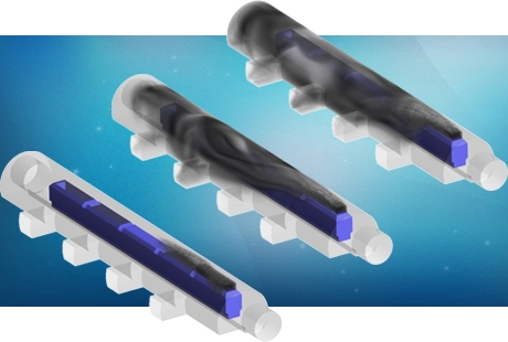
In very rare instances the venting/flaring system cannot cope with the pressure increase leading to a plastic collapse failure of the processing equipment or piping. Leakage and spilling happen with subsequent explosion risk and environmental damage. CFD multi-phase models are used to predict the impact of these leaks, either in liquid or gas form and either happening on the surface (to the atmosphere) or subsea. CFD diffusion models are broadly used to determine the plume of contaminants in the surroundings of the failure helping the designer to dimension mitigation measures. These models also provide crucial information to determine the risk of explosion due to the concentration of hydrocarbons.

Spillage events are often controlled by the emergency shutdown system (ESD). However in other occasions an explosion is triggered before that happens. A correct safety planning would require the operator to take the possibility of this event into consideration on the risk assessments and layout designs. Blasts can be modelled using CFD analysis. The chemical interactions and exothermal reactions occurring on a gas explosion are input to the CFD model that would predict the pressure wave spread. This pressure pattern is then used on FEA linear and non-linear models to predict the expected damage on the failing device and the surrounding equipment.
For more information on other services for offshore rigs and platforms, please go to the oil and gas rig tab or contact us here.
Our services for this sector
Blow-out prevention
- BOP stack linear-elastic FEA stress analysis
- Non-linear plastic FEA analysis for annular and ram BOP valves
- Kick development CFD model with non-Newtonian fluid properties
- ASME and API compliance assessments for BOP stack and flanges
Venting
- Venting valves thermal and stress FEA analysis
- De-pressuring system configuration assessment
- ASME VIII Div 2 compliance assessments for relief valves
- Joule-Thomson cooling studies for high velocity venting releases
Flaring
- Thermal/radiation calculations on the flare tip
- Flare stack design according to thermal and mechanical requirements
- API 521 compliance assessments for flaring devices
- Corrosion and flash back studies for the flare tip
Spillage and explosion
- Gas diffusion CFD models for exhaust and gas venting
- Oil diffusion calculations on spillage events offshore
- Steam and chemical explosion on different parts of the processing
- Vessel and pipeline blast modelling


