Subsea S.U.R.F. and manifolds
The complexity of subsea gathering and pipeline systems has dramatically increased over the last 10 years. With more stages of processing being run on the seabed and fields with increasingly distributed production and injection wells, an efficient subsea pipeline layout is paramount. Hub-and-spoke or ring flow-line layouts are the most common. The correct dimensioning of the whole system including pipelines, manifolds, risers and umbilicals require skills and experience drawn from a number of different engineering disciplines.
 Process dimensioning and expected produce composition, pipe deployment and installation, material selection, erosion and corrosion and multi-phase fluid dynamics are just a few areas to consider when designing an offshore subsea umbilicals, risers and flowlines system. In most of those areas the engineers are increasingly relying on computational techniques such as finite element analysis (FEA) and computational fluid dynamics (CFD) to acquire valuable design insight.
Umbilicals
One of the most challenging connections of a subsea development with the surface is the umbilical. The umbilical is a composite cable containing hydraulic pipes, tension wires, electrical power, control and communication signals. These can be either independent cables or can be integrated with flowlines and risers, with the subsequent thermal/mechanical interactions.

 Fluid dynamics studies on variable pressure conditions for the fluids being transported, thermal studies considering all umbilical functions and surrounding flowlines and buoyancy and marine interactions are just a few examples.
The outcome of CFD analysis for umbilicals is often used to assess the mechanical performance of certain features and connections using FEA. This is especially important on all umbilical interfaces with other fixed equipment such as the Umbilical Termination Structure (UTS), the surface platform or moored buoyancy modules. Bend stiffeners and other connection features can also be modelled and optimised using non-linear FEA models.
Risers
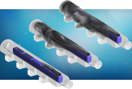
Similar to the umbilical lines, risers connect the subsea installation with the surface processing and offloading facilities. Usually insulated to withstand sea temperatures, risers can be either rigid or flexible and a variety of configurations can be chosen according to the marine conditions, depth and expected production flow rate and composition. On topside processing developments, risers often transport a multi-phase fluid containing gas, oil and condensates. Predicting the fluid dynamics performance of this multi-phase mixture on varying pressure and thermal conditions is often too complex to rely on hand calculations only. CFD models play a vital role in the prediction of plugs, bubbles and slugs in the risers under steady operation conditions. In addition CFD can be used to study transient thermal events such as; condensate freezing and hydrate formation in a riser during a shut-in; or the effectiveness of a riser start-up procedure.

Finite element analysis has also become increasingly applied to riser mechanical and stress calculations. Riser attachments, connections to the seabed and fasteners onto floating rigs/platforms are subject to significant static loads – such as self-weight, steady current drag or buoyancy forces – and potentially more damaging dynamic/oscillating loads – such as those due to vortex-induced-vibration (VIV), wave-induced motion or even transient in-line pressure fluctuations. The complex combinations of these static and dynamic loads may result in catastrophic fatigue damage. PRE Technologies possesses an extensive background in stress and fatigue calculations for a variety of riser and flow-line configurations, taking into account the relevant dynamic loading and using FEA tools to predict fatigue life/damage in accordance with relevant industry Standards.
Manifolds
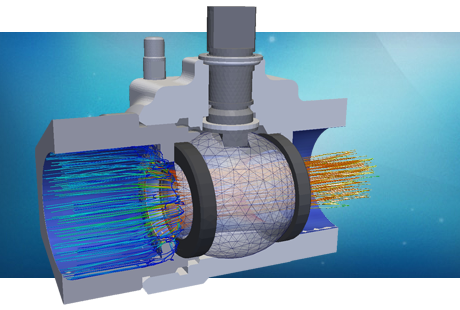
Risers and other flow-lines are typically gathered and connected to manifolds. The purpose of manifolds is to collect and distribute fluids according to production and processing needs. A steel body with drilled cavities and a number of valves and connections form the manifold system which is often fixed to the seabed. The system must be designed to withstand corrosion and erosion as well as the internal and external mechanical loads. These typically consist of; the in-line pressure, the external hydrostatic pressure, marine induced loadings, installation loading and ROV operation loadings.

In addition, manifold protection cages are often provided to shield the manifold against extreme external loading such as trawl-loads or loads from the impact of dropped-object such as anchors. CFD and FEA have become widely used in the design and optimisation of manifold systems. Based on our previous experiences, PRE Technologies recommends the modelling of manifold operational and limit conditions in order to prevent un-expected production interruptions and reduce safety hazards.
Pipelines
The design, deployment and installation of long pipelines and flowlines constitutes a massive engineering challenge, especially in ultra-deep water environments. In order to address the risks involved, all gatherings, transmission lines, and distribution pipeline systems must be designed and operated according to industry Codes, Standards, and Regulations. Pipe fittings, valves, and flanges are also designed, sized and manufactured in accordance with several industry guidelines and Standards including API, ASTM, ASME and Manufacturer’s Standardization Soc. (MSS).

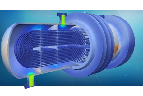
The pipeline components have to be designed and sized to handle the net fluid pressure loading, the bending stresses due to installation and in service loading, as well as flow induced vibration loads and thermal-mechanical loading due to pipeline thermal expansion. Pipeline bends and turns must also be carefully located to avoid thermally induced stresses on the pipeline and the connecting equipment. FEA analysis has proven to be an excellent choice for complex pipeline stress calculations involving both thermal and mechanical loads.
On pipeline installations part of the costs is caused by damage created by flow induced vibration (FIV). The origin of this effect can be either, inner flow instabilities and turbulence caused by obstacles in the flow, or exterior currents causing the
 turbulent boundary layers to separate from the tubular structure and create vortex shedding which could eventually culminate into vortex-induced-vibration (VIV).
Flowlines experiencing FIV can eventually fail due to fatigue. The likelihood of failure due to FIV under different operational conditions can be determined using a coupled CFD - FEA methodology. In addition, the effectiveness of design modifications aimed at suppressing FIV, such as helical strakes or fairings, can be assessed using the same CFD-FEA approach. A CFD analysis of the unsteady turbulent fluid flow is used to predict the dynamic fluid forces on the structure. Signal processing techniques are used to extract the key frequency composition of the unsteady fluid force loading. Using this, together with an FEA modal analysis for the frequency response of the structure, a FIV damage risk assessment can be carried out.
For more information on other services for subsea systems, please go to the subsea services tab or contact us.
Our services for this sector
Umbilicals
- Thermal and mechanical FEA calculations on umbilical lines
- Stress, vibrational and fatigue studies on umbilical termination structures (UTS)
- ASME and API compliance assessments for connections and fixtures
- Fluid dynamics assessment of working fluids on different thermal conditions
Risers
- Flow assurance CFD analysis for risers
- Stress, vibrational and fatigue studies on riser terminations
- ASME and API compliance assessments for connections and fixtures
- Multi-phase CFD modelling for different produce compositions
- VIV studies for vibration prevention
Manifolds
- Stress, vibrational and fatigue studies for manifolds and valves
- Erosion and corrosion CFD analysis on manifolds
- ROV's operations loading assessment on valve actuators
- Dropped object calculations on manifolds and shield cages
Pipelines
- Flow assurance CFD analysis for pipelines and flowlines
- Stress, vibrational and fatigue studies on pipe terminations and flanges
- ASME and API compliance assessments for connections and fixtures
- Multi-phase CFD modelling for different produce compositions
- VIV studies for vibration prevention


