Oil processing
Typical offshore production rigs have an oil processing line consisting of a subsea or on-rig Christmas tree, a series of stages for separation of oil, gas and water, a coalescence device and a desalting facility. Normally a number of heat exchangers and pumps will also be needed on different sections of the process.
 It takes a good team of chemical and process engineers to design the process flow and the heat and material balance which then translate into operationally successful oil processing facilities.
However, the design work does not end there. More detailed fluid dynamical studies on the different separation processes, evaluations of the effects of marine dynamics on the equipment performance, erosion and fatigue calculations and thermal analyses are often required to quantify sub-system risks and reduce uncertainties at the Front End Engineering and Design (FEED) stage of a production facility.
Separation
The well often produces a combination of crude oil, gas, condensates, water and various contaminants which must be separated and processed. The production separators come in many forms and designs depending on the production fluid composition and their performance greatly depends on aspects such as flow rates, fluid properties, vessel configuration and internal fixtures.
 Gas often come partially out of solution from the pipeline because of pressure drop across an upstream choke or a control valve, however an appropriate inlet device is needed on the separator to obtain an initial bulk separation of liquid/gas. Slugs and foaming issues normally occur and engineers strive to develop new solutions to minimise their impact. Flat or dish-head plates, vanes of different geometries or cyclonic inlets are constantly evolving to cope with higher momentum inlets whilst avoiding foam generation, short-circuiting and channelling stream effects.
On the flow distribution zone of the separator, flow straighteners such as a single perforated baffle plate or a full-diameter plate allow the gas/liquid to flow more uniformly after leaving the vane-type inlet, inlet cyclones, or even the impact plates. The plate also acts as an impingement demister and foam breaker as well. Engineers need to determine the net-free area (NFA) according to the fluid shearing needed for the particular application.
On the inlet and flow distribution areas of the separator, CFD analysis becomes extremely helpful. Multi-phase modelling for different fluid interactions, flow rates, slug formation and momentum can be used to assess different inlet/distribution configurations on the separator. Additionally, aspects such as erosion due to the high kinetic energy of the fluid can be analysed using CFD combined with statistical modelling.
The next stage on the separator would be the coalescing zone, where the dispersed droplets/bubbles will settle at a velocity determined by the balance between gravity and viscous drag forces acting on the droplets/bubble.

CFD based droplet/bubble trajectory calculations can be used to determine a relationship between vessel length and droplet/bubble cut-out diameters for a given flow rate. Aspects such as fluid turbulence or the effect of the internals such as plate or matrix packs or other shearing devices on the flow patterns can also be accounted for using CFD models. PRE Technologies has a strong background in applying these modelling techniques to simulate a range of expected operational conditions and optimising vessel configurations in a quick and relatively in-expensive manner.
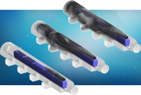
Studies such as mechanical or thermal stress and fatigue analyses, erosion and corrosion models and thermal shocking prediction are often required. In addition to these, for equipment located on floating rigs or FPSOs, marine dynamics and its influence on production must be considered. Sloshing studies can be performed using computational fluid dynamics and in addition to separation efficiency, the hydrodynamic loading on flow straighteners, baffles and other devices can be determined for different oscillation conditions (oscillation direction, frequency and amplitude).
Our white paper on gravity separation can be found here.
Other equipment
Crude oil may need to be re-conditioned to ensure proper processing. Oil heaters could be located in certain stages of the process, typically between separation stages, to reheat the oil/water/gas mixture, reduce viscosity and promote separation.
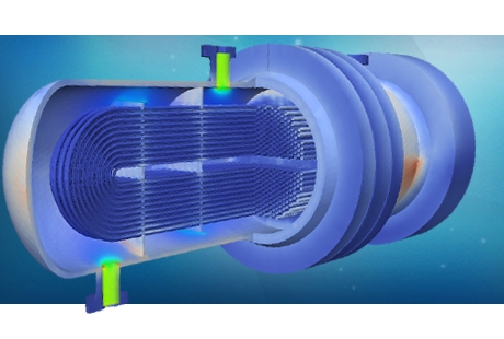
 It will also make it easier to separate out water when initial water cut is high and temperature is low. Different heat exchangers are used depending on the production composition but tube/shell type are the most common. Heat exchangers are often subject to high pressures and temperature loading that is oscillatory in nature. It is of paramount importance to assess the likelihood of failure due to high stress (pressure and thermal loading), fatigue (oscillating loading) and erosion wear. A combination of CFD and FEA analyses has historically been used for these purposes.
After the third stage separator, the oil is often diverted to a coalescer for final removal of water. Extensive engineering skill and experience are required to design this piece of equipment. Aspects such as the geometry and separation of the internal electrodes, the field intensity and frequency, or the materials and coatings used are just some critical aspects of the design. Empirical formulas and experience guide most of these designs. However CFD and FEA analyses can assist designers in some facets such as mechanical design (stress and fatigue), erosion and corrosion predictions or even short-circuit prevention for different coalescer grid layouts and production mixture compositions.

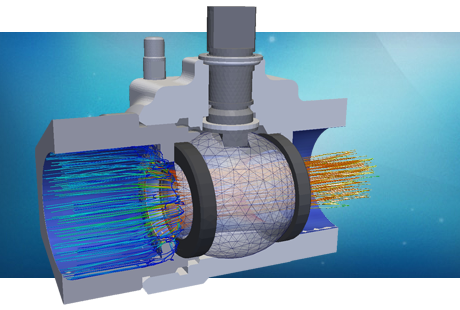
A large variety of other pieces of equipment are used on oil treatment and processing facilities. Devices such as gas/liquid cylindrical cyclones (GLCC) or bulk oil treaters (BOT) are also used frequently. Physical principles vary from system to system but all of them can take advantage of mathematical modelling and virtual prototyping. Mixing, separation and other multi-phase studies combined with thermal analysis and mechanical assessments will help designers and operators design and troubleshoot their oil processing installations. Over the years, PRE Technologies’ engineers have availed their unique set of engineering skills, computational capability and customer-oriented focus to aid some of the key players in the market.
For more information on other services for processing systems, please go to the processing services tab or contact us here.
Our services for this sector
Oil and gas separation
-
FEA studies
- ASME and API compliance assessments for separator vessels
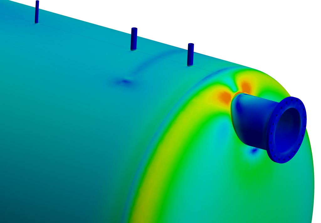
- Stress and fatigue predictions on separator vessel's connections and flanges
- Separator vessel thermal stress and fatigue FEA calculations
- Separator's interiors and features mechanical optimisation
-
CFD studies
- Fluid dynamical assessment on separator's inlet device (slugs and foam)
- Sloshing studies on offshore processing units
- Flow distribution zone optimisation using CFD analysis
- Efficiency study for different produce compositions and flow-rates
Oil heating and cooling
- ASME and API compliance assessments for plate and tube-and-shell HE
- Stress, vibrational and fatigue studies for heat exchangers
- Thermal performance optimisation of heat exchangers


