FE and CFD based analysis of valves
Background
The extreme operating conditions of any offshore Oil & Gas facility constitute a unique technical challenge involving a vast number of engineering disciplines. Valves and their piping play a vital role in this industry. Numerical simulation has proven to be key in supporting valve design optimisation and accelerating product development while reducing innovation costs.
PRE Technologies’ engineering team, with their comprehensive range of CFD and FEA expertise and subsea experience, is a valuable partner for this process. This article presents these capabilities and illustrates some of the valuable insights that FE and CFD analyses can bring to topsides and subsea valve design.
In this paper we cover four of the analysis capabilities PRE Technologies offer for valve manufacturers and operators:
- Erosion prediction
- Fluid induced vibration (FIV/VIV)
- Joule Thomson cooling (J-T cooling)
- ASME VIII, API 6 and DNV assessments
Erosion prediction
Erosion is the phenomenon of part’s material loss due to collision forces induced by solid particles, liquid droplets or bubbles from cavitation events. Different approaches have been taken historically, involving different degrees of complexity.
Currently most CFD erosion studies use a three-stage approach:
- The fluid flow is modelled first
- Particle trajectories are calculated explicitly (velocity and impact angle are obtained)
- Erosion damage is obtained using erosion laws
CFD tools and the experienced PRE Technologies team can provide reliable models to estimate the velocity of the particles and the angle function in order to accurately predict the expected erosion rates for complex geometries under different environments.
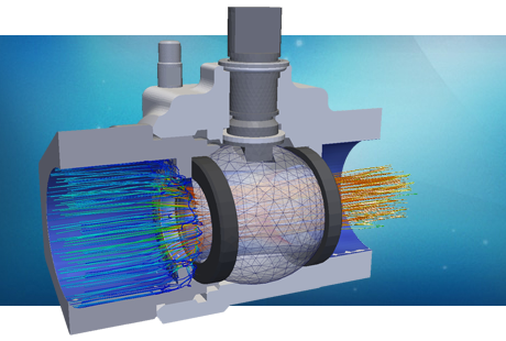
The following two figures present an erosion test case on a ball valve. The figure on the left presents the fluid-dynamics solution of the system together with the particles tracking in the flow. The number and intensity of impacts of sand particles on the valve interiors' surface are recorded (velocity and angle). The post-processing of the results then provides results of the expected wear with time, typically in mm/year. The figure on the right presents a map of the expected wear for this particular example.

You may find more information regarding PRE Technologies’ capabilities in the field of Erosion analysis in our single-topic CFD erosion modelling white paper.
Fluid Induced Vibration (FIV/VIV)
Production and injection pipelines for oil and gas developments are designed to operate in severe flow regimes, with flow speeds often in the range of 15 m/s – 40 m/s and fluid flows far from homogeneous. As a result, the flow around piping inserts can become detached creating an unsteady wake with vortices being periodically shed from the obstacle body. The following figure (left hand side) represents a valve/pipe section system where a probe has been placed for fluid sample collection. The video on the right presents the pressure iso-surfaces showing the pressure periodical fluctuation.
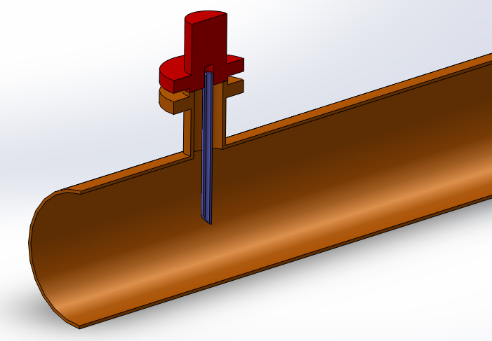
Vortices are alternately shed from one side to another, at a shedding frequency which is linearly proportional to the flow speed, and lead to the formation of a von-Karman vortex street. The next two figures present this effect, in side view (left) and plan view (right).


A clearer view of the vortex shedding can be obtained plotting the vorticity of the fluid (next two figures), in isometric view (left) and plan view (right).


Using the CFD-predicted hydrodynamic loading together with signal processing techniques, the forcing frequency due to vortex shedding may be obtained. A FFT (fast Fourier transform) of the lift coefficient signal is used to extract the frequency composition and determine the dominant forcing frequencies.
This forcing frequency information together with a FEA based modal analysis of the valve/pipeline configuration, to obtain the structural mode shapes and natural frequencies, can be used to assess the likelihood of VIV occurring (potential resonance effects). The next two figures present the first two modes of vibration of the valve/pipe section system. The first resonant mode is shown on the left and the second mode on the right.
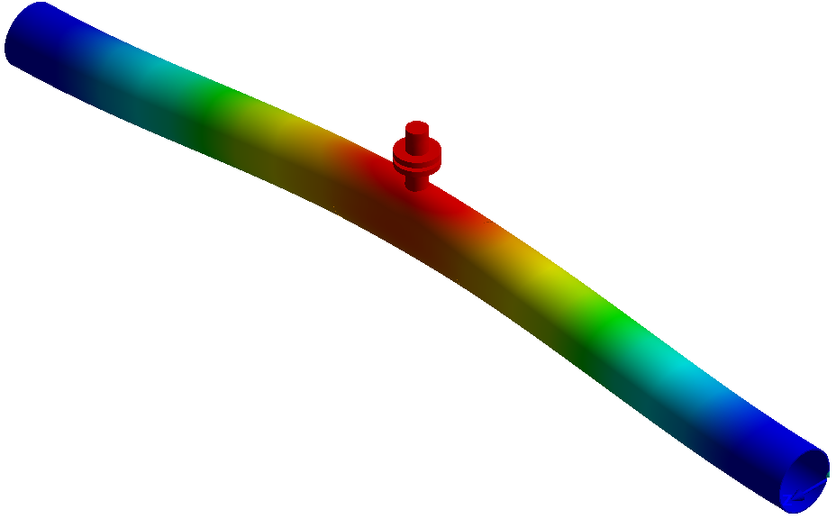

More details regarding PRE Technologies’ capabilities in the field of VIV modelling and analysis can be found in our CFD VIV modelling white paper.
Joule-Thomson effect (J-T Cooling)
The sudden expansion of the production fluid may lead to supersonic flows and cryogenic temperatures developing downstream of the choke. This temperature change due to the expansion is referred to as Joule-Thomson (J-T) cooling. The very low temperatures resulting from a J-T cooling event may result in hydrates formation, material embrittlement and other undesirable consequences.
PRE Technologies possess experience in modelling this effect. Unsteady 3D CFD models are used to simulate the pressure drop across choke valves and subsequent temperature drop downstream.
The next two figures present the results of a gas production well Xmas tree. The left hand side picture presents the gas velocity distribution on the valve and the right hand side picture the temperature contour.


You may find more information regarding PRE Technologies’ capabilities in the field of J-T cooling modelling in our single-topic CFD based J-T cooling modelling white paper.
ASME VIII, API 6 and DNV assessments
In the past engineers studying vessel and piping performance have developed a set of rules based on experience and testing (Design by rules). All this knowledge was condensed in the Codes and Standards that now serve as guidelines for the calculations required in the design process.
The ASME VIII design by analysis rules require verifications associated with 4 failure modes:
- Protection against plastic collapse
- Protection against local failure
- Protection against collapse from buckling
- Protection against failure from cyclic loading
All of the above must be assessed to ensure the valve's design compliance with the standard and can be performed via linear and non-linear numerical analyses. API 6 also refers to ASME VIII Standard for methodology definition so the procedure briefly described herein also applies to API codes.
This section of the white paper outlines the technical approach PRE Technologies recommends for the performance of the structural analysis of valves subject to pressure with ASME VIII rules, for the mentioned four failure modes.
Protection against plastic collapse
PRE Technologies possess significant experience in the assessment of this failure mode for a variety of valve designs, both subsea and topsides: Gate, needle, check, ball and choke valves.
Protection against plastic collapse is performed via a detailed finite element stress analysis of the structure under investigation. Three methodologies can be used for this verification:
- Elastic Stress Analysis – Linear elastic FEA
- Limit-Load Method – Linear FEA (small displacements) with non-linear material properties.
- Elastic-Plastic Analysis – Full non-linear FEA.
Most types of analysis include a results post-processing stage that includes the stress classification (primary, secondary and peak stresses) as well as the linearization of stresses along the carefully selected stress classification lines (SCLs).
PRE Technologies specialise not only in the most common linear-elastic analyses, but also in the more complex elastic-plastic analyses. The next three figures present the results from a elastic-plastic analysis for a subsea valve component. The levels of plastification of the the wetted surfaces become problematic as we increase the pressure levels over the design pressure for the component.

More information about this methodology can be found in our Stress and fatigue modelling white paper.
Protection against local failure
Protection against local failure can be performed in concurrence with the analysis for plastic collapse. It consists of a component-by-component analysis aimed at preventing the potential for fracture in the design under investigation.
Two methods exist, in accordance with the analysis type:
- Elastic analysis
- Elastic-plastic analysis
Local failure is assessed by customised tools to determine the local damage based on the limiting triaxial strain (εL), residual manufacturing strains (εcf) and equivalent plastic strains (εpeq), defined as follows:
Local damage can then be determined as the sum of the utilisations for each load case, Dε(k), and the residual manufacturing damage, Dεform.

Protection against buckling
Buckling is often an irrelevant failure mode on valves due to most valves’ typical sturdy design. However it can play a vital road in the piping sections and spools connecting valves both topsides and subsea.
Buckling is a bifurcation behaviour which occurs when an increase in the level of compressive load can lead to more than one analytical result. The behaviour is highly non-linear and small defects or changes in the geometry can trigger significantly different results.


As a consequence, buckling can lead to catastrophic failures at loads which are well below the compressive yield strength. Thus, the safety factor involved in establishing protection against buckling can be very high. ASME VIII provides three routes to assessing the protection against buckling of a design:
- Linear buckling with elastic stress analysis
- Linear buckling with elastic-plastic stress analysis
- Non-linear buckling with elastic-plastic stress analysis
All of these involve establishing a design factor, ФB, which must be satisfied. Capacity reduction factors, βcr, are used in the definition of the design factor.
Protection against fatigue
Protection by cyclic loading is achieved by ensuring that the damage incurred by cyclic loading does not exceed the allowable number of cycles.
You may find more information regarding PRE Technologies’ capabilities in the field of Fatigue analysis in our Thermo-mechanical fatigue modelling white paper.
Other studies for valve designers
PRE Technologies have experience in other CFD/FEA studies applied to valve design:
- Flow coefficient calculation (Cv)
- Elastic-plastic mechanical assessment
- Mechanically and thermally induced fatigue calculations
- Dropped object analysis
- Flange assessment
Please see other related articles and case studies available at the PRE Technologies website. We are constantly updating our website and aim to have a wider range of case studies in the future, so do keep in touch.
Keep your curiosity in good shape.
For more information on this or any other technical white paper, please contact us.


