Advantages of finite element analysis (FEA)
What is it about?

Typically, mechanics and heat transfer problems are initially tackled with analytical tools. Where the geometry and physics are sufficiently simple, this yields accurate results. Applying simplifications intelligently can increase the level of complexity which is possible to analyse.
The reality of complex industrial products and processes is that simple physical relations are quickly replaced by complex partial differential equations and complicated geometries. Many resort to experimental testing of prototypes to bypass the knowledge gap. Doing so requires significant investment of time and resources and does not always yield the certainty which is sought.
An alternate solution is the use of advanced computational tools such Finite Element Analysis (FEA). FEA’s main advantage is that it produces a much more detailed set of results than experimental investigations and is often quicker and less expensive.
Fundamentally, it relies on the discretisation of the geometry to solve mechanical and thermal equations, effectively subdividing the structure in an assembly of simple (finite) elements. Instead of tackling a big problem directly, we divide it into smaller and more easily solvable problems and then get a unique result for the system as a whole. The discrete model is an approximation of the behaviour of the real physical structure. However, provided that the discretisation mesh is dense enough, the approximation is sufficient to accurately model reality.

The advantages of FEA are numerous:
- Comprehensive result sets, generating the physical response of the system at any location, including some which might have been neglected in an analytical approach.
- Safe simulation of potentially dangerous, destructive or impractical load conditions and failure modes.
- Optimal use of a model. Often, several failure modes or physical events can be tested within a common model.
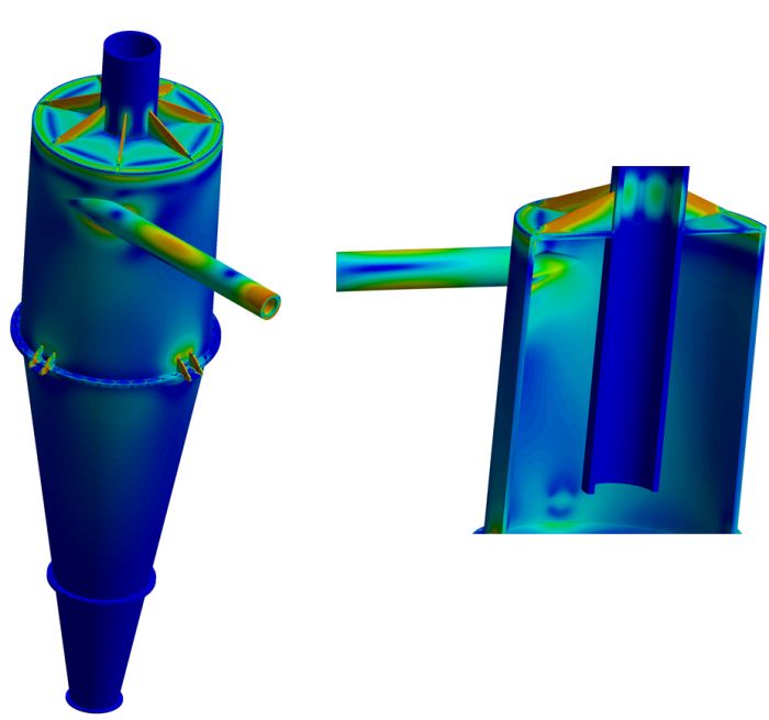
- The simultaneous calculation and visual representation of a wide variety of physical parameters such as stress or temperature, enabling the designer to rapidly analyse performance and possible modifications.
- Extrapolation of existing experimental results via parametric analyses of validated models.
- Relatively low investment and rapid calculation time for most applications.
Finite element solution process
The set of equations and the process by which they are solved varies depending on the problem (thermal, mechanical, linear, non-linear) as well as the software used to compute it. Nevertheless, the general structure is common to all finite element methods:
- Discretise the structure into smaller elements, creating a mesh.
- Assemble the elements at the nodes, implementing the required contacts and boundary conditions between the different model components, to form a system of equations approximating the real solution.
- Solve the system of equations using computational resources.
- Post-process the results to compute the desired quantities (e.g. stress, displacement, temperature) for the entire domain.
The benefits of FEA include the visual representation of stress or temperature gradients throughout the part as well as enabling the designer to rapidly analyse modifications in the product or process.
Types of FE analyses
The number and types of FE analyses spans the whole spectrum of physical behaviours and interactions. Generally speaking, the finite element method represents mechanics as the interaction between a set of elements with simplified physical behaviour. In its most simple incarnation, elements are effectively a spring with a size and stiffness. The system can then be described as the response of the system, defined by a stiffness matrix (K), to a force applied (F), in terms of displacement matrix (x); i.e. F = K x.

Linear FEA presumes that the stiffness matrix (i.e. the material properties, geometrical configuration and boundary conditions) for the case does not change significantly during the course of analysis. This is a good approximation for cases where the structure and the conditions of the analysis are not expected to change significantly because of the load applied. The numerical simplification leads to significant computational and cost savings.
Non-linearities become important when conditions are more complex. A typical example is when the material properties change with force, such as in plasticity. Defining complex material models allows the accurate modelling of the non-linear plastic response of structures, useful for the prediction of failure modes (PRE Technologies white paper on elastic-plastic analysis of pressure vessels).
Other types of non-linearities are encountered when the structural problems are subjected to dynamic problems, linear and non-linear buckling, modal and vibration analysis or combinations of the above.

Heat transfer can also be computed via the finite element method with the added advantage that the thermally induced deformation and stresses can be easily determined and combined with other types of analyses. Multi-physics modelling allows coupled fluid-structure interaction modelling, opening the range of possible simulations scenarios to the most complex engineering problems, greatly reducing the cost of integrating mechanical, thermal and fluid dynamic phenomena.
Applications
The practical advantages of using FEA have led many sectors to make it a fundamental part of their design processes. PRE’s engineering expertise and the skillsets available in our team have focused our projects on the following sectors:
FEA for Heat Exchange products
FEA for Pressure Containing products
FEA for Plastics and Composites
A variety of modelling techniques are used in our daily operations, but most of our projects are related to thermally and/or mechanically induced stress and fatigue, vibrations and modal analyses or buckling studies. We have published abridged versions of some of our projects to showcase our analytical and computational capabilities. FEA studies include:
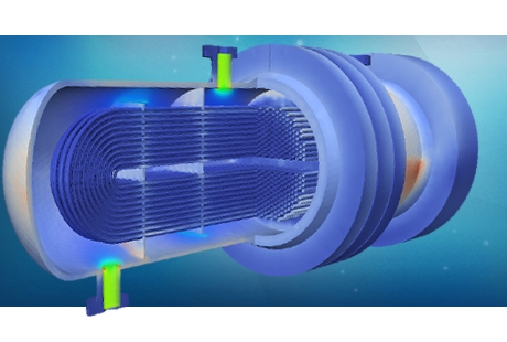
- Tube and shell heat exchanger (mechanical/thermal/fatigue FEA)
- Oil and gas separator vessel (mechanical FEA)
- Water/sand Hydrocyclone (mechanical FEA)
- Oil and gas subsea umbilical (mechanical FEA)
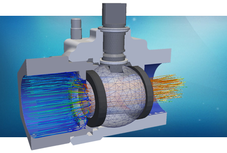
- Multi-phase flow valves (mechanical/thermal FEA)
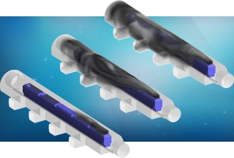
- Light and electronics heat sinks (thermal FEA)
- Industrial pneumatic clamp (mechanical FEA)
- Industrial structure joint (mechanical FEA)
- Hydraulic cylinder (mechanical FEA)
- Oil and gas subsea spool (mechanical/fatigue FEA)
Please contact us for more information about the Finite Element Method and to learn how it can help your product and process design.
Click the following link to learn more about our FEA services.
Go here to learn more about finite element method.


